ESPHome Wired Smart Speaker Setup
PCM5102A
PCM5102A has additional soldering requirements in order to work well with esphome. There are a couple of pads on its back that need to be solder bridged.
H1L (FLT) = L
H2L (DMP) = L
H3L (XMT) = H
H4L (FMT) = L (most important, sets the audio format to I2S)

SCK to GND bridging may also be necessary in case of weird sound.
https://community.home-assistant.io/t/i2s-audio-with-pcm5102a/739461
#Speaker

i2s_audio:
  i2s_lrclk_pin: GPIO27
  i2s_bclk_pin: GPIO25

media_player:
  - platform: i2s_audio
    name: SmartSpeakerPlayer
    dac_type: external
    i2s_dout_pin: GPIO26
    mode: stereo
Connecting PCM5102A with ESP32 – ETH01 (WT32 – S1)
i2s_audio:
i2s_lrclk_pin: GPIO15
i2s_bclk_pin: GPIO14
media_player:
- platform: i2s_audio
name: "SmartSpeakerPlayer"
dac_type: external
i2s_dout_pin: GPIO02
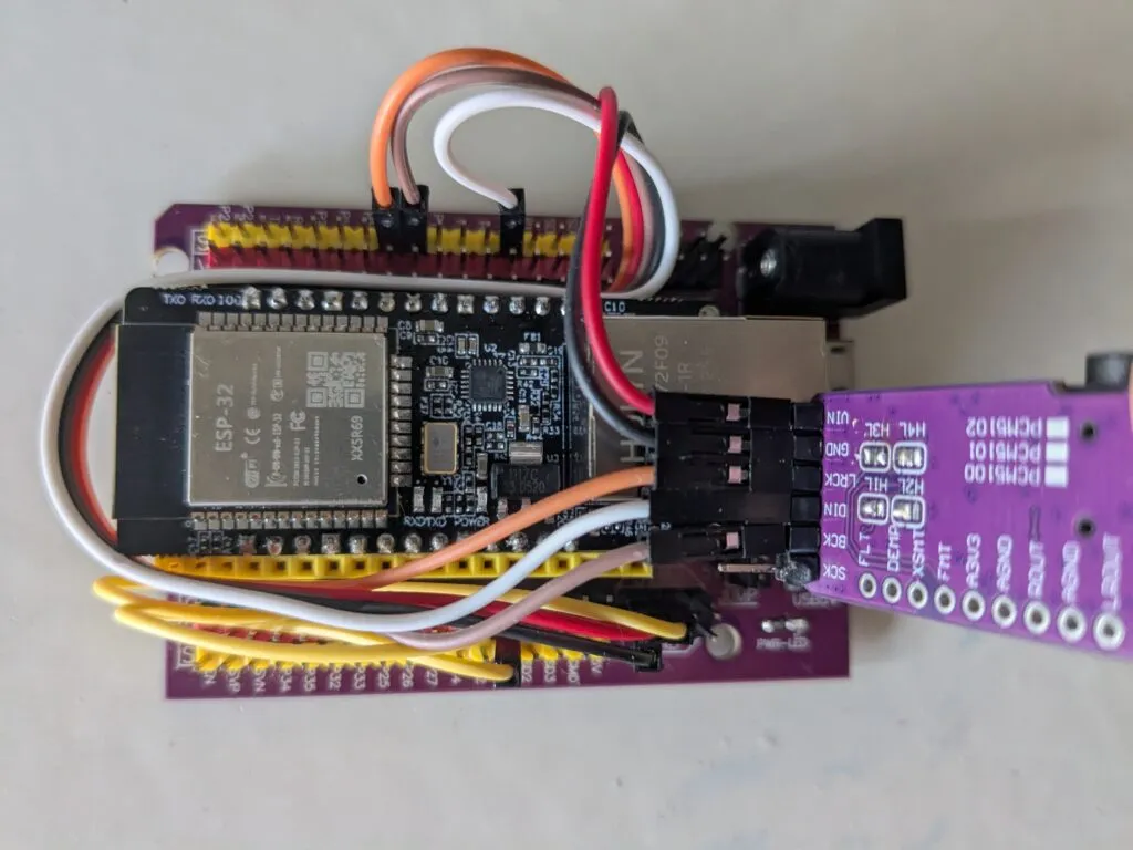
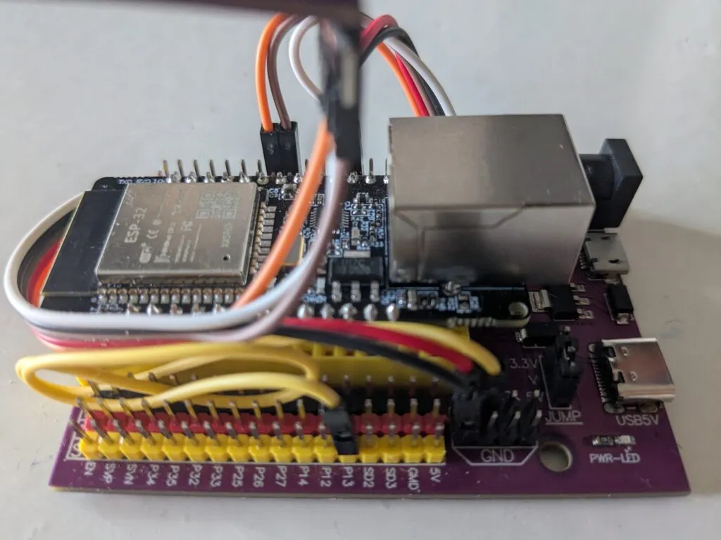
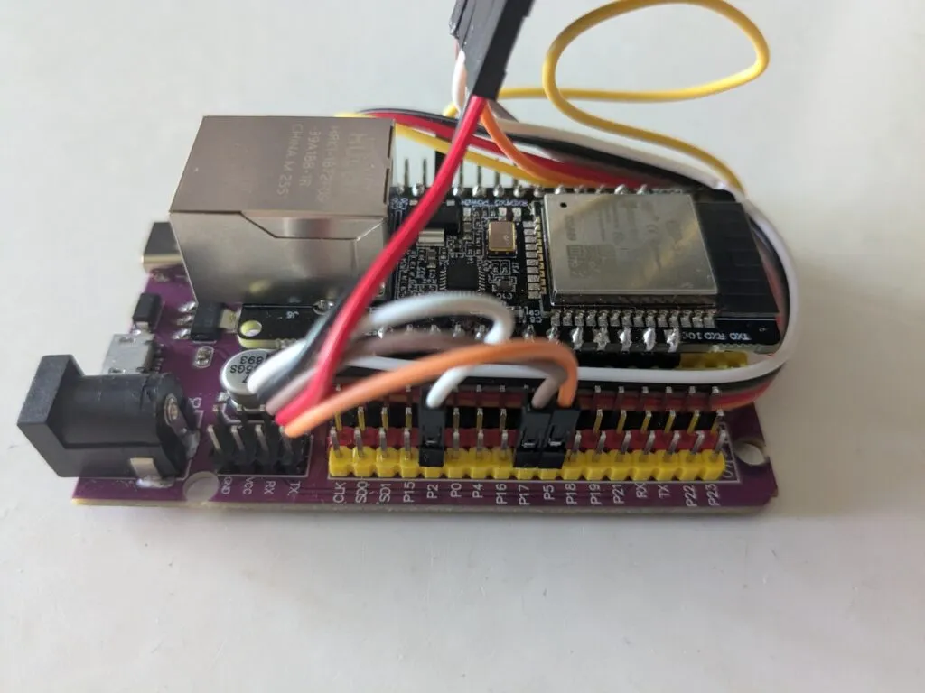
mode: stereoMake sure the ESP32 – ETH01 (WT32 – S1) TX0 and RX0 pins are plugged into the corresponding slots of the development board. Wire as follows:
| ESP32 – ETH01 (WT32 – S1) | Development Board | PCM5102A |
| GND (Development Board) | GND (Black) | |
| 5V (Yellow) | P13 (Yellow) | VIN (Red) |
| GPIO15 | P5 (Orange) | LCK (Orange) |
| PIO02 | P2 (White) | DIN (White) |
| GPIO14 | P17 (Brown) | BCK (Brown) |
Example config:
esphome:
name: smartspeakername
friendly_name: SmartSpeakerName
esp32:
board: esp32dev
framework:
type: arduino
# Disable logging
logger:
level: NONE
# Enable Home Assistant API
api:
encryption:
key: "here-should-be-an-api-key"
ota:
- platform: esphome
password: "b371b140f68a4f7df40569258ae5840a"
ethernet:
type: LAN8720
mdc_pin: GPIO23
mdio_pin: GPIO18
clk_mode: GPIO0_IN
phy_addr: 1
power_pin: GPIO16
i2s_audio:
i2s_lrclk_pin: GPIO15
i2s_bclk_pin: GPIO14
media_player:
- platform: i2s_audio
name: "SmartSpeakerPlayer"
dac_type: external
i2s_dout_pin: GPIO02
mode: stereo
button:
- platform: restart
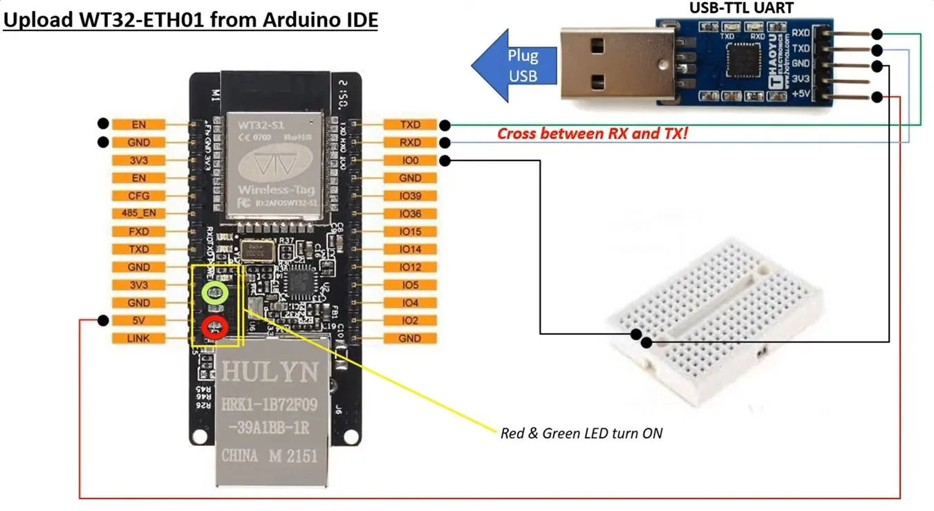
name: "SmartSpeakerPlayer Restart"ESP32 – ETH01 (WT32 – S1) doesn’t have usb input. It need a special input device (USB-TTL UART) a bit of wiring and only then it is possible to flash the code.
- Connect RX, TX, VCC(5+), and GND.

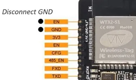
- Connect EN – GND
 Disconnect EN – GND
- Flash the device as usual. https://web.esphome.io/?dashboard_wizard
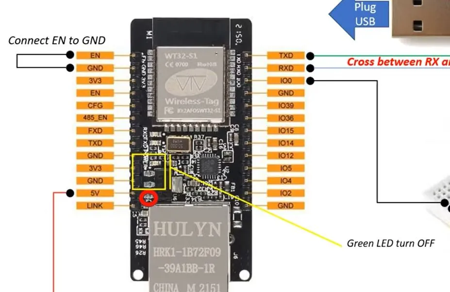 Disconnect EN – GND