ESPHome Wired Smart Speaker Setup
This is a simple Ethernet connected speaker to transmit audio. It’s sole purpose is to play notification sounds or music.
PCM5102A
PCM5102A has additional soldering requirements in order to work well with esphome. There are a couple of pads on its back that need to be solder bridged.
H1L (FLT) = L
H2L (DMP) = L
H3L (XMT) = H
H4L (FMT) = L (most important, sets the audio format to I2S)

SCK to GND bridging may also be necessary in case of weird sound.
https://community.home-assistant.io/t/i2s-audio-with-pcm5102a/739461
#Speaker

i2s_audio:
  i2s_lrclk_pin: GPIO27
  i2s_bclk_pin: GPIO25

media_player:
  - platform: i2s_audio
    name: SmartSpeakerPlayer
    dac_type: external
    i2s_dout_pin: GPIO26
    mode: stereo
Connecting PCM5102A with ESP32 – ETH01 (WT32 – S1)
i2s_audio:
  i2s_lrclk_pin: GPIO15
  i2s_bclk_pin: GPIO14

media_player:
  - platform: i2s_audio
    name: "SmartSpeakerPlayer"
    dac_type: external
    i2s_dout_pin: GPIO02
    mode: stereo
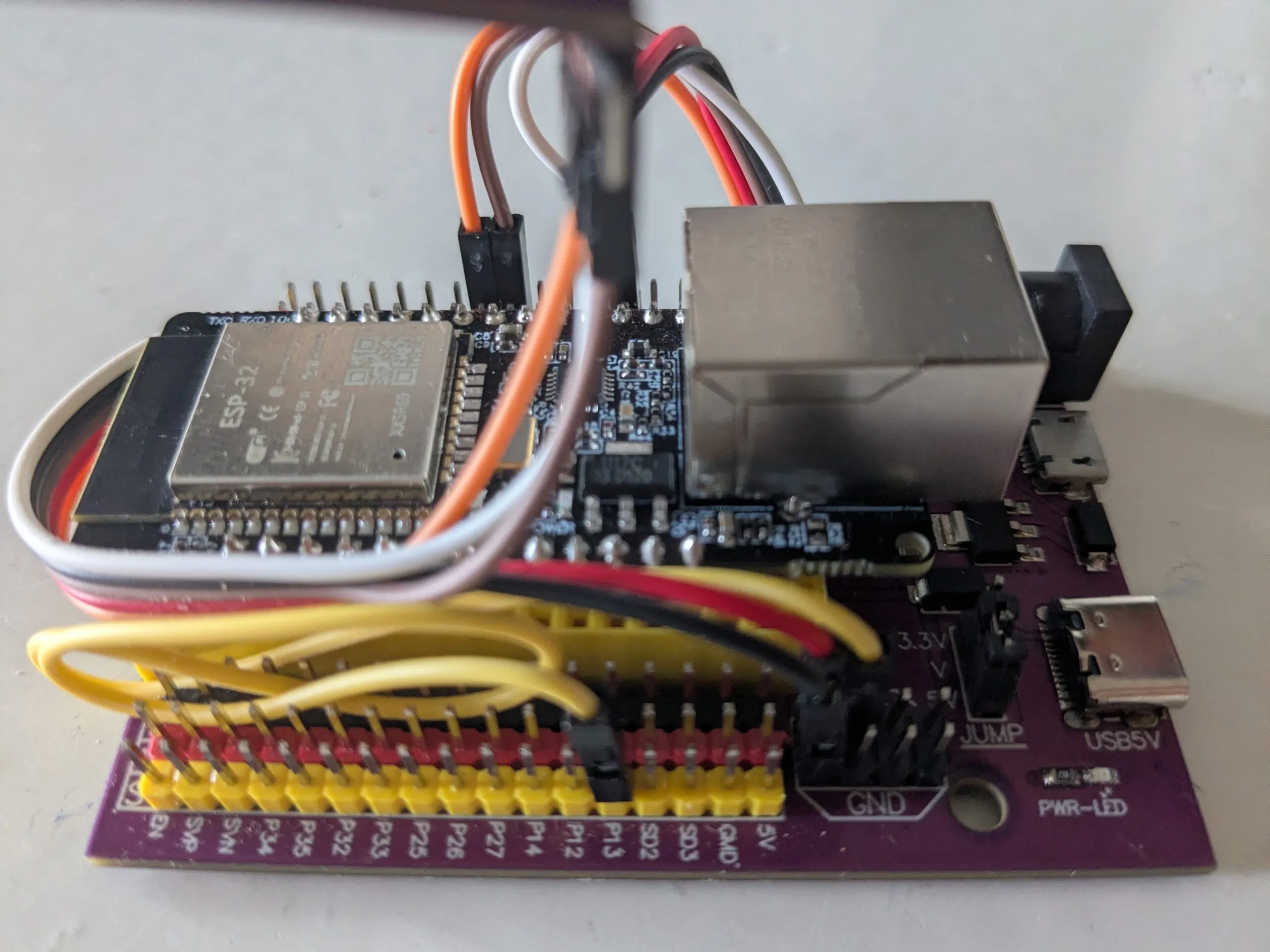
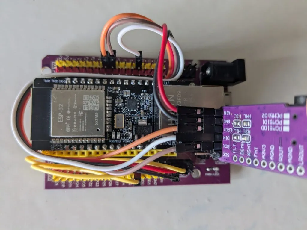
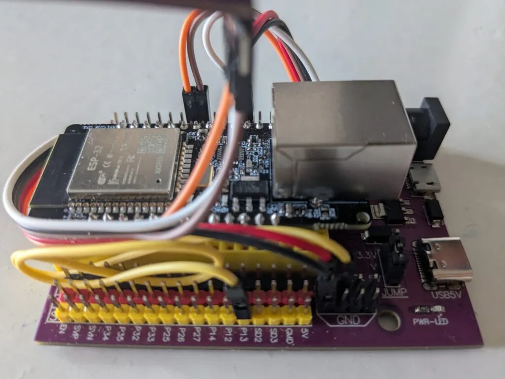
Make sure the ESP32 – ETH01 (WT32 – S1) TX0 and RX0 pins are plugged into the corresponding slots of the development board. Wire as follows:
| ESP32 – ETH01 (WT32 – S1) | Development Board | PCM5102A |
| GND (Development Board) | GND (Black) | |
| 5V (Yellow) | P13 (Yellow) | VIN (Red) |
| GPIO15 | P5 (Orange) | LCK (Orange) |
| PIO02 | P2 (White) | DIN (White) |
| GPIO14 | P17 (Brown) | BCK (Brown) |
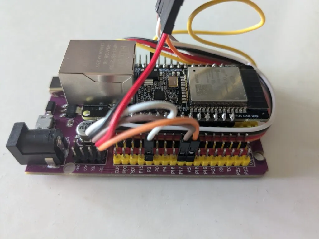
Example config:
esphome:
  name: smartspeakername
  friendly_name: SmartSpeakerName

esp32:
  board: esp32dev
  framework:
    type: arduino


# Disable logging
logger:
  level: NONE

# Enable Home Assistant API
api:
  encryption:
    key: "here-should-be-an-api-key"

ota:
  - platform: esphome
    password: "b371b140f68a4f7df40569258ae5840a"

ethernet:
  type: LAN8720
  mdc_pin: GPIO23
  mdio_pin: GPIO18
  clk_mode: GPIO0_IN
  phy_addr: 1
  power_pin: GPIO16

i2s_audio:
  i2s_lrclk_pin: GPIO15
  i2s_bclk_pin: GPIO14

media_player:
  - platform: i2s_audio
    name: "SmartSpeakerPlayer"
    dac_type: external
    i2s_dout_pin: GPIO02
    mode: stereo

button:
  - platform: restart
    name: "SmartSpeakerPlayer Restart"
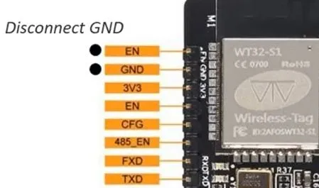
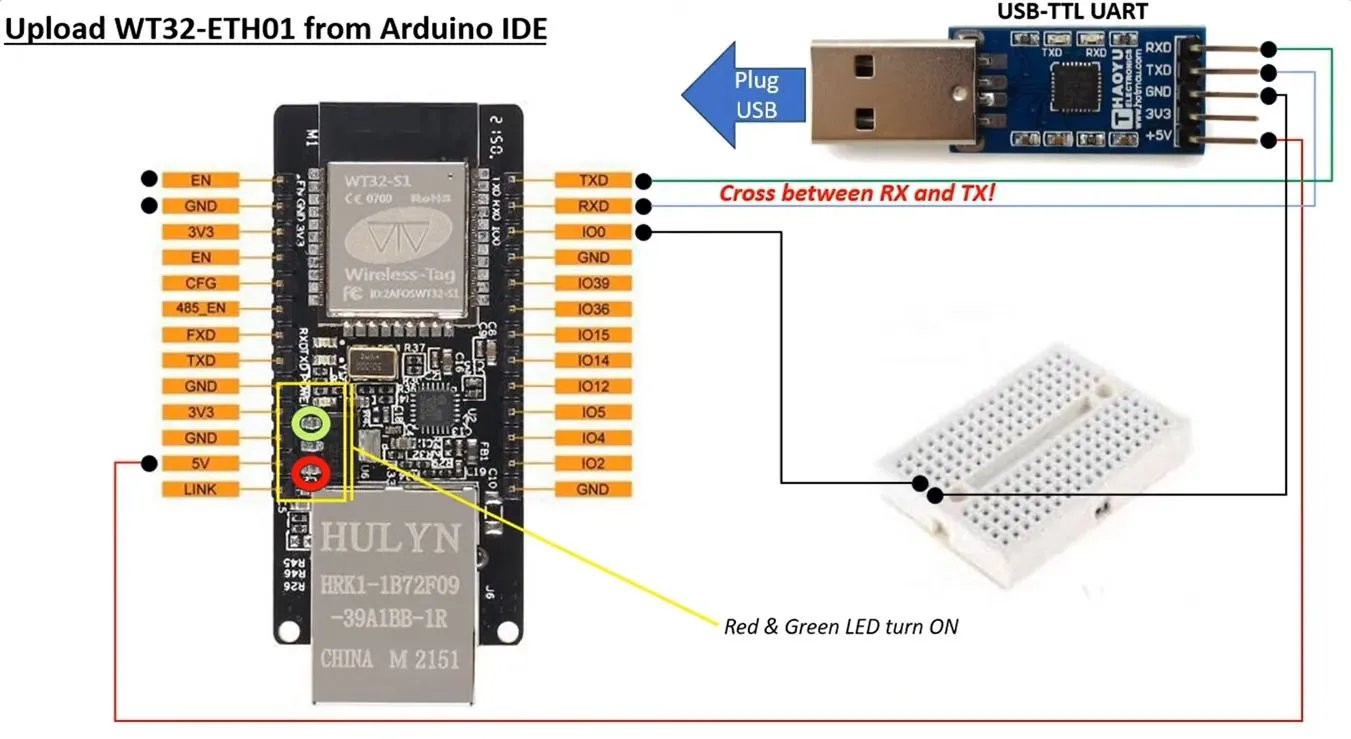
ESP32 – ETH01 (WT32 – S1) doesn’t have usb input. It need a special input device (USB-TTL UART) a bit of wiring and only then it is possible to flash the code.
- Connect RX, TX, VCC(5+), and GND.

- Connect EN – GND
 Disconnect EN – GND
- Flash the device as usual. https://web.esphome.io/?dashboard_wizard
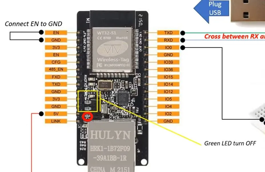 Disconnect EN – GND